Updated
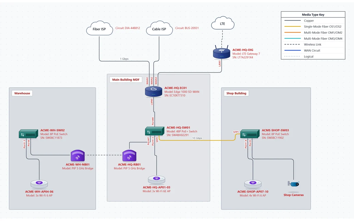
A small campus drawn the way it's usually built: two ISPs and an LTE backup into an SD-WAN edge in the main building's MDF, a 10 Gbps single-mode fiber run to the shop building, a 5 GHz point-to-point bridge to the warehouse, and the switches, access points and cameras in each building with their port labels. A second page shows the same network as VLANs and subnets.
Two pages in one file: the physical network and the logical (VLAN) view. Rename the devices and it becomes your site.
A fiber ISP (1 Gbps DIA with its circuit ID and a /29 public block), a cable ISP and an LTE gateway land on WAN1, WAN2 and WAN3 of the SD-WAN edge, which feeds the 48-port PoE+ core switch.
Main Building MDF, Warehouse and Shop Building are areas, so each building's switch, access points and cameras stay together when you move it or auto-arrange the page.
SFP1 to SFP1 over single-mode fiber at 10 Gbps to the shop switch, and a 5 GHz point-to-point bridge pair to the warehouse switch, each end with its port.
Corporate VLAN 10 (10.10.10.0/24), Voice VLAN 20 (10.10.20.0/24) and Guest Wi-Fi VLAN 99 (192.168.99.0/24), with SVIs on the core, PCs, a domain controller, a printer, desk phones and the PBX.
One printer on the logical page sits at 10.10.11.25, outside VLAN 10's subnet, on purpose. Click Check in the editor and the network check points straight at it.
The MDF (main distribution frame) is the room where the carrier circuits land and the core usually sits. IDFs (intermediate distribution frames) are the smaller closets that serve each floor or building and uplink back to the MDF. A campus diagram is mostly about how those rooms connect: which uplink, how fast, over which media, and into which ports at each end. That's what someone needs when a building drops off the network.
In NetworkSketch every building and wiring closet is an area. The template uses a room area for the MDF and a site area for each of the other two buildings. If a building has its own closet, add a room area named for it (say, "IDF 2 - Warehouse") inside the building and put that closet's switch in it. Uplinks are cables, not lines: each has a media type, a speed and a port label at both ends, and the media type key on the page lists every media you used.
| Media | Typical campus use | Standard reach at 10 Gbps |
|---|---|---|
| Copper, Cat6A | Inside a room, switch to switch or to a nearby closet | 100 m (10GBASE-T) |
| Multi-mode fiber, OM3 | MDF to IDF inside one building | 300 m (10GBASE-SR) |
| Multi-mode fiber, OM4 | Longer risers inside a building | 400 m (10GBASE-SR) |
| Single-mode fiber, OS2 | Between buildings | 10 km (10GBASE-LR) |
| Point-to-point wireless | Where you can't trench fiber | Depends on the radio and the path |
Reach figures are the IEEE 802.3 distances for each PHY; check the optics you actually buy. For jacket and connector colors, see the fiber color code chart.
Keep the logical view on its own page. The physical page answers "where is it and how is it cabled"; the VLAN page answers "which subnet is it in and what's its gateway". Mixing both on one drawing is how campus diagrams turn into spaghetti. The template's two pages share hostnames, and the network check reads both, so an IP given to two different devices is caught even when they're on different pages.
About fifteen minutes for a small site if you have the switch list in front of you.
Click Open this template. It loads in the editor with no account. Your edits autosave in your browser as you go.
In Document Settings, set the title, customer and street address that print in the title block. Click any device to change its hostname, model, serial and management IP.
Rename and resize the building areas, add a room area for each IDF, and drag switches into the room they live in. Moving an area moves everything inside it.
Click a link to set its media type, speed and the port at each end. Add the cable ID, length and test result if you want them in the cabling schedule.
On the Logical (VLANs) page, set each VLAN's ID, subnet and gateway, then click Check to find duplicate IPs and addresses outside their subnet.
Run Auto-arrange if the page got messy, click Mark verified today, and export a PDF with the device inventory, cabling schedule and VLAN table.
Every template opens in the same editor, so you can copy devices and areas from one into another.
The MDF (main distribution frame) is the main telecom room, where carrier circuits arrive and the core switch or router usually sits. An IDF (intermediate distribution frame) is a smaller closet that serves a floor or a building and uplinks back to the MDF, usually over fiber.
Yes. Add an area for each building or wiring closet, or give each building its own page and connect the pages with Page Link shapes. It stays one file and one PDF.
No. It doesn't scan or connect to your network. You enter what's there, paste a device list from a spreadsheet, or import from SolarWinds Orion. The network check then reviews what you entered.
Opening and editing it in your browser is free, with no account. Saving the file and exporting the PDF need the free 14-day trial (just your email, no credit card). After that, editing it needs Pro: it has 19 devices on two pages, more than the Free plan's 10 devices on one page. Pro is $9 a month billed yearly, or $15 month to month, and CallSketch is included.
No signup to look around. Rename the buildings, set your uplinks, and start the trial when you want the PDF.
Open this template