For managed service providers

An MSP client network diagram you can hand to the client

Updated

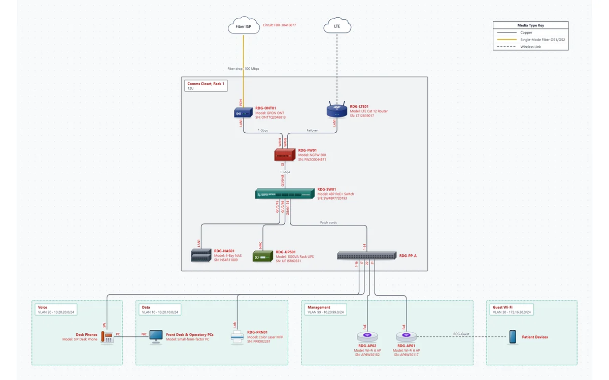
A small-business site documented the way a managed service provider hands it over: the fiber circuit and LTE failover, one 12U rack with the firewall, PoE switch, patch panel, NAS and UPS, four VLANs with their DHCP settings, and every cable with an ID, a length and a test result. The example client is a dental office; the layout fits most small offices.

On your phone? The editor is made for a computer. Email yourself a link and open the template at your desk. Email me a link for my computer
Opens the real editor in your browser. No account needed to look around; the free 14-day trial (no credit card) adds saving and PDF export.
MSP client branch template: fiber ISP and LTE failover into a firewall in a comms closet rack with a switch, patch panel, NAS and UPS, feeding voice, data, management and guest Wi-Fi VLANs

What's in this template

One page for the whole site. The sample PDF shows what the client gets.

Circuits with support details

A 500/500 Mbps fiber ISP with its circuit ID, a /30 public block and the carrier's support number and account, through the ISP's ONT. An LTE router on WAN2 is failover only.

The comms closet rack

Rack 1 (12U): firewall at U10, patch panel at U9, 48-port PoE+ switch at U8, NAS at U4 (4 x 8 TB, RAID 6) and a 1500VA UPS at U1-2 with its runtime. Serials and asset tags on each.

Four VLANs

Data 10 (DHCP .100-.199 from the firewall), Voice 20 (DHCP with option 66), Guest Wi-Fi 30 (client isolation) and Management 99, each with its subnet and gateway.

Labeled cabling

Patch panel ports to 16 desk phones (with the PCs plugged into the phones), a printer and two access points with their SSIDs. Cable IDs, lengths and Pass results throughout.

What a client handover pack should contain

When a client changes providers, or a tech who's never been on site takes the after-hours call, a picture isn't enough. They need to know what each box is, where it sits, who to call about the circuit and which cable goes where. The template's sample PDF is that pack: four pages from one file.

In the packWhy the client or the next tech needs itWhere it comes from
The diagram, with a title blockClient name, site address, author, approval and a verified date on every pageDocument Settings
Device inventoryModels, serials and asset tags for warranty claims and renewals; management IPs for remote accessEach device's fields
Circuit detailsCircuit ID, bandwidth, public IPs and the carrier's support number for the outage callThe ISP / Carrier device
VLAN / subnet tableSubnets, gateways and DHCP scopes, which change hands with the firewallThe VLAN areas
Cabling scheduleSwitch port to patch panel to wall jack, with cable IDs, lengths and test resultsEach link's fields
Change logWhat changed, when and by whom, with your ticket numberDocument Settings

Keep one file per client site, named the way your ticketing system names the client. Files are plain, documented JSON saved wherever you choose, so they live in your own documentation system or the client's SharePoint, not on our servers. The subscription is per account, not per client or per device, so documenting one more site costs nothing extra.

Before handing over, click Check: it flags duplicate IPs, addresses outside their VLAN's subnet, a switch port used by two cables and MAC addresses that don't look right. Then Mark verified today so the client can see when the diagram last matched the site. For what auditors ask clients for, see network documentation for audits.
How to adapt it to your network

Bring the closet photos and the switch config; the rest is typing.

  1. 1

    Open the template

    Click Open this template. No account needed to look around.

  2. 2

    Set the client details

    In Document Settings, enter the client name, site address and author. They print in the title block on every page.

  3. 3

    Walk the closet

    Rename each device and fill in model, serial and asset tag. Put the rack and U in Location, as the template does (Rack 1, U8).

  4. 4

    Record the circuit

    Set the circuit ID, bandwidth, public IPs and the carrier's support number on the ISP device. Mark the failover link.

  5. 5

    Label the cabling

    For each link, set the port at both ends, the VLANs it carries, and the cable ID, length and test result from your certifier.

  6. 6

    Check, verify, export

    Click Check, fix what it finds, Mark verified today, and export the PDF and a CSV for the client's records.

Related templates

Every template opens in the same editor, so you can copy devices and areas from one into another.

Questions

Can we reuse it for every client?

Yes. Finish one site the way you like it, save it as a file, and open that file as the starting point for the next client. One subscription covers all of them.

Does it pull data from our RMM or PSA?

No. It doesn't connect to devices or to other tools. You can paste a device list from a spreadsheet (an export from your RMM, for example), or import from SolarWinds Orion.

Is client network data sent to NetworkSketch?

No. The editor runs in your browser and diagrams are saved as files on your computer. There is no server copy, so we aren't another vendor holding your clients' topology. Security details.

Is the template free to use?

Opening and editing it in your browser is free, with no account. Saving the file and exporting the PDF need the free 14-day trial (just your email, no credit card). After that, editing it needs Pro: it has 13 devices, more than the Free plan's 10 devices on one page. Pro is $9 a month billed yearly, or $15 month to month, and CallSketch is included.

Open the MSP client template in your browser.

No signup to look around. Swap in your client's gear, and start the trial when you want the PDF.

Open this template